Monday, August 24, 2009

Transformer

Pole-mounted single-phase transformer with center-tapped secondary. Note use of a grounded conductor as one leg of the primary feeder.

A transformer is a device that transfers electrical energy from one circuit to another through inductively coupled conductors — the transformer's coils. A varying current in the first or primary winding creates a varying magnetic field through the secondary winding. This varying magnetic field induces a varying electromotive force (EMF) or "voltage" in the "secondary" winding. This effect is called mutual induction.

If a load is connected to the secondary, an electric current will flow in the secondary winding and electrical energy will be transferred from the primary circuit through the transformer to the load. In an ideal transformer, the induced voltage in the secondary winding (VS) is in proportion to the primary voltage (VP), and is given by the ratio of the number of turns in the secondary (NS) to the number of turns in the primary (NP) as follows:

\frac{V_{S}}{V_{P}} = \frac{N_{S}}{N_{P}}

By appropriate selection of the ratio of turns, a transformer thus allows an alternating current (AC) voltage to be "stepped up" by making NS greater than NP, or "stepped down" by making NS less than NP.

In the vast majority of transformers, the coils are wound around a ferromagnetic core, air-core transformers being a notable exception.

Transformers come in a range of sizes from a thumbnail-sized coupling transformer hidden inside a stage microphone to huge units weighing hundreds of tons used to interconnect portions of national power grids. All operate with the same basic principles, although the range of designs is wide. While new technologies have eliminated the need for transformers in some electronic circuits, transformers are still found in nearly all electronic devices designed for household ("mains") voltage. Transformers are essential for high voltage power transmission, which makes long distance transmission economically practical.

Saturday, August 22, 2009

Basic Electrical Overview-Basic wiring

You don't have to be an electrician to replace a light fixture. Many homeowners are afraid to tackle electrical projects—and rightly so. If improperly handled, electricity poses electrocution and fire hazards. But simple jobs like light fixture replacements are easy and safe if you follow a few simple rules. Lowe's is happy to provide this information as a service to you.

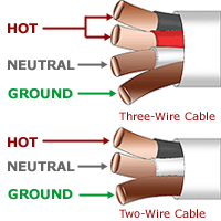
The most basic principles of the wiring in your home are simple. The following is elementary information from which every homeowner can benefit:Labeled wiring.

  • In contemporary wiring, individual wires run in a sheathed cable. "Two-wire with ground" and "three-wire with ground" cables are available. Two-wire with ground cables have a black wire, a white wire and an uninsulated ground. Three-wire with ground cables have a black wire, a white wire, a red wire and an uninsulated ground. Older houses may have "knob and tube" wiring—a two-wire system. With this system, individual wires are insulated with white or black treated fabric.

  • Regardless of the type of wiring in your home, the white wire is usually the neutral wire, the black wire is "hot," and the exposed copper wires are ground wires. The white wire is sometimes used as a hot wire because some wiring installations require it. In this case, the white wire should be coded black with paint or electrical tape. Note, however, that it is possible that whoever did the wiring may not have coded the wire. If a red wire is present, it should also be hot.

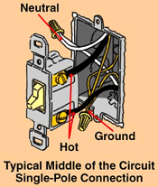
  • Connections.Switches may be wired at the end or in the middle of a circuit. If only a single cable enters the box (or one set of black and white wires), the fixture is at the end of the circuit. This is usually, but not always, the situation with ceiling light fixtures. If two cables enter the box (or two sets of black and white wires in older "knob and tube" installations), the fixture is in the middle of a circuit. A third cable (or set of black and white wires) may also enter the fixture, depending upon the installation. The placement of the fixture within the circuit affects how it is wired.

  • The black, or hot wires, are connected to the brass screw terminals on receptacles and switches. The neutral wires are connected to the silver terminals. Ground wires should not be ignored. They should be connected to each other, to the grounding screw terminals (painted green) on receptacles, and to grounding screws in metal electrical boxes when metal boxes are used.

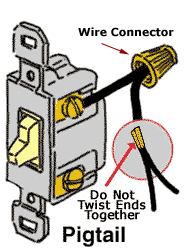
Pigtail.

  • Pigtail leads are short wires which are connected to terminals on receptacles or switches. The leads are then connected to the home wiring using plastic wire connectors. Codes in some areas require that pigtails be used on all standard receptacle connections. Always use pigtails when more than one wire must be connected to a single terminal.

Important!

What If Your House Has Aluminum Wiring?

It is easy to tell if your home has aluminum wiring—the metal under the insulation is almost white instead of copper colored. Aluminum and copper wires should be connected with a wire connector specifically rated for this purpose. Otherwise, copper and aluminum will react with each other, possibly leading to a loose connection and creating a fire hazard.

Was this information helpful? Please let us know your do-it-yourself experiences. We'd love to hear from you!

These How-To's are provided as a service from Lowe's, the Original Home Improvement Warehouse of How-To information for the World Wide Web. The information in Lowe's "How-To" clinics is intended to simplify jobs around the house. Tools, products, materials, techniques, building codes and local regulations change; therefore, Lowe's assumes no liability for omissions, errors or the outcome of any project. The reader must always exercise reasonable caution, follow current codes and regulations that may apply, and is urged to consult with a licensed professional if in doubt about any procedures.

Thursday, August 20, 2009

The Garden Hose

When the resistance increases, and the current is constant, the pressure increases:

The same thing is true of electrical circuits:

If R increases, V has to increase to keep their quotient (I) constant.

would happen to the pressure if you decrease the flow (by turning down the faucet) while keeping the nozzle on the hose (constant resistance)?

Wednesday, August 19, 2009

Current, Voltage, and Resistance

These three are related by a very simple equation:

Take a minute and reflect on the relationship between these three components. Think of it like it's a garden hose:

The current is water flowing in the hose. The water pressure is analogous to the voltage of a circuit and the diameter of the hose determines the resistance.

happens when you put a nozzle on end of the hose? In this case, the resistance increases with a constant amount of water flowing through it. What happens to the pressure?

Monday, August 17, 2009

The Basic Electrical Circuit

Electrical circuits involve 3 basic components:

is the force created by the separation of charges. Kind of like when two opposite poles of a magnet are put close together, but are separated by a short distance. A force tries to pull them together. When there are more negative charges on the inside of the membrane of a cell, there is a force driving positive charges inward to neutralize them. The unit of voltage is the volt and it is represented by the symbol V. Voltage is also called "potential" or "potential difference".

is a measure of how hard it is for charges to move in the system. In a cell, the lipid portion of the membrane is impermiable to ions, so the resistance to current across the membrane is determined by the opening and closing of ion channels. When the channels open, the resistance decreases. When they close, resistance increases (because ions can't move through the membrane). The units of resistance are ohms and it is represented by the symbol R. (Note - When talking about channels, "conductance" is usually used instead of resistance. Conductance is the inverse of resistance (1/R), or how easy it is to pass charges. Its units are seimans [S].)

is the movment of charges. In an electrical circuit, electrons move from the negative pole to the positive pole (although electrical current is defined as the movement of positive charges, so current is said to go from the positive pole to negative pole - go figure). In cells, current is when ions move through the membrane (usually Na+, K+, Ca2+, or Cl-).

Sunday, August 16, 2009

Basic Electricity - Electrical Definition

Basic electricity is described in many ways. When an electric circuit flows through a conductor, a magnetic field (or "flux") develops around the conductor. The highest flux density occurs when the conductor is formed into a coil having many turns. In electronics and basic electricity, a coil is usually known as an inductor. If a steady DC current is run through the coil, you would have an electromagnet - a device with the properties of a conventional magnet, except you can turn it on or off by placing a switch in the circuit.

Basic Electrical Theory
There are four basic electrical quantities that we need to know:

  • Current
  • Potential Difference (Voltage)
  • Power
  • Resistance
Electrical Current
Current is a flow of charge. Each electron carries a charge of 1.6 × 10⁻¹⁹ coulombs. This is far too small to be any use, so we consider electricity to flow in packets called coulombs. When there is a flow of 1 coulomb per second, a current of 1 amp is flowing. Current is measured in ampères, or amps (A).

Potential Difference
Potential difference is often referred to as voltage. There are several ways of defining voltage; the correct physics definition is energy per unit charge, in other words, how big a job of work each lump of charge can do.

Power in a Circuit
Power in a circuit can be worked out using the simple relationship:

Power (W) = Voltage (V) × Current (A)

Electrical Resistance
This is the opposition to the flow of an electric current.

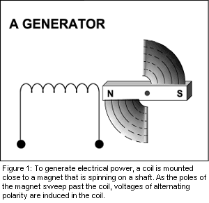
There's reciprocity in the interaction between electron flow and magnetism. If you sweep one pole of a magnet quickly past an electrical conductor (at a right angle to it), a voltage will be momentarily "induced" in the conductor. The polarity of the voltage will depend upon which pole of the magnet you're using, and in which direction it sweeps past the conductor.

This phenomenon becomes more apparent when the conductor is formed into a coil of many turns.

basic electricity

Figure 1 shows a coil mounted close to a magnet that is spinning on a shaft. As the north pole of the magnet sweeps past the coil, a voltage is induced in the coil, and, if there is a "complete" circuit, current will flow. As the south pole of the magnet sweeps past, a voltage of opposite polarity is induced, and current flows in the opposite direction.

This relationship in basic electricity is the fundamental operating principle of a generator. The output, known as alternating current, is the type of power that electric utility companies supply to businesses and homes. A practical generator would likely have two coils mounted on opposite sides of the spinning magnet and wired together in a series connection. Because the coils are in a series, the voltages combine, and the voltage output of the generator will be twice that of each coil.

Figure 2 is a graph of the voltage produced by such a generator as a function of time. Let's assume that this happens to be a 120-volt, 60-Hz generator. The voltage at one point in the cycle momentarily passes through 0 volts, but it's headed for a maximum of 169.7 volts. After that point, the voltage declines, passing through 0 volts, then reverses its polarity, and has a negative "peak" of -169.7 volts.

This curve is known as a sine wave since the voltage at any point is proportional to the sine of the angle of rotation. The magnet is rotating 60 times a second, so the sine wave repeats at the same frequency, making the period of a single cycle one-sixtieth of a second.

Electricity appears in two forms: alternating current (AC) and direct current (DC). Direct current does not change directions-- the electron flow is always from the negative pole to the positive pole-- although as we mentioned before, the electrons themselves don't really "move," it's the holes that are created that "move." Direct current is almost always what is used inside of electronic devices to power the various internal components, but it is a harmful thing in audio signals, which are alternating current. Alternating current does change direction-- standard household electricity is alternating current, because of its flexibility in traveling long distances. It changes direction at a specific frequency-- 60 times per second, or 60 Hz (in the United States, Japan, and a couple of other countries; in Europe the standard is 50 Hz). Audio signals vary their direction-alternation according to the frequency in question.

AC - ALTERNATING CURRENT
Alternating current or AC electricity is the type of electricity commonly used in homes and businesses throughout the world.

While the flow of electrons through a wire in direct current (DC) electricity is continuous in one direction, the current in AC electricity alternates in direction. The back-and-forth motion occurs between 50 and 60 times per second, depending on the electrical system of the country.

AC is created by an AC electric generator, which determines the frequency. What is special about AC electricity is that the voltage in can be readily changed, thus making it more suitable for long-distance transmission than DC electricity. But also, AC can employ capacitors and inductors in electronic circuitry, allowing for a wide range of applications.

DC - DIRECT CURRENT
In a direct-current system, it's easy to determine voltage because it is nonvarying or varies slowly over time. You can simply make a measurement with a DC voltmeter. But in an AC circuit, the voltage is constantly changing.

Electrical engineers state the voltage of an AC sine wave as the RMS (root-mean-square), a value equal to the peak value of the sine wave divided by the square root of two, which is approximately 1.414. If you know the RMS voltage, you can multiply it by the square root of two to calculate the peak voltage of the curve. If you were to power a light bulb from 120V(RMS) AC, you would get the same amount of light from the bulb as you would by powering it from 120V DC. Yet another device uses electromagnetic induction: the transformer.

Just as an iron core improves the inductance of a coil, it has the same positive effect in a transformer, and most power transformers are wound on iron cores.

In order to understand how electricity is created and works it is necessary to look at how all matter is structured. All matter is made up of molecules that have a certain number of atoms, for example one molecule of water is made up of two atoms of hydrogen and one of oxygen giving a symbol of H 2 O. All other matter also has a symbol like this and is made up of atoms.

To be able to understand electricity however, the atom must be broken down even further into a nucleus, electrons and protons. The nucleus is made up of positively charged protons and neutrally charged neutrons that generally balance the number of negatively charged electrons, which are moving around the nucleus in a similar manner to the planets circling the sun.

The outer ring of electrons is called the Valency Shell and the electrons contained in this ring are called Valence Electrons. These are the electrons which are knocked or forced out to form a flow of electricity. If one or more electrons are moved out of the the atom it will leave the atom with more protons than electrons, which means that the atom will be positively charged.

  • One rule that is very prevalent in all forms of electricity, and also magnetism, is that like charges, or poles, repel and unlike charges, poles, will attract. This means that a positively charged object will attract a negatively charged one, but if both charges are the same then they will repel each other.

Saturday, August 15, 2009

Test your knowledge - Electrical


1. The unit of measurement of electrical current produced in a circuit by 1 volt acting through a resistance of 1 ohm?

Amp
Volt
Watt
Ohm


2. If the Voltmeter reading is 12V, and the Ammeter reading is 3A, what is the resistance?

4 Amps
4 Ohms
36 Ohms
4 Volts


3. The unit of measurement of electrical resistance. The resistance of a circuit in which a potential difference of 1 volt produces a current of 1 ampere.

Volt
Watt
Amp
Ohm


4. An electromagnetic device for changing the voltage of alternating current (AC) electricity.

Winding
Stator
Transformer
Rotor


5. A device consisting of two conducting surfaces separated by an insulator and having the ability of storing electric energy.

Diode
Capacitor
Resistor
Vacuum Tube


6. An element of an electron tube or semiconductor device that takes part in conduction, such as the plate, anode, cathode and filament.

Electrode
Diode
Capacitor
Resistor


7. The ratio of watts to volt-amperes of an AC electric circuit.

Horse Power
Resistance
Power Factor
Inductance


8. The stationary part of a rotating electric machine. Commonly used to describe the stationary part of an AC machine that contains the primary windings.

Rotor
Stator
Core
Winding


9. The preferred terminology for cycles per second (frequency).

Hertz (HZ)
RPM
Ohm
Farad


10. A unit of capacity that will store one coulomb of electrical charge when one volt of electrical pressure is applied.

Hertz (HZ)
Capacitance
Inductance
Farad


11. A piece of rigid metal within a panel or fusebox which distributes electricity to the various circuits by means of their connection to it.

Busbar
Terminal
Contact
Splitter


12. A device that interrupts current to its circuit by melting apart. It must then be replaced.

Circuit breaker
Fuse
Diode
Wire


13. The flow of electrons in a wire.

Amp
Volt
Current
Inductance


14. A measure of the work electricity can do.

Watt
Horse Power
Amp
Foot-pounds


15. A material is considered to be a conductor of electricity if it has?

Multiple neutrons
No electrons
No neutrons
Free electrons


16. The most commonly used conductor of electricity is?

Aluminum
Copper
Mercury
Gold


17. Resistance is measured in?

Ohms
Watts
Volts
Amps


18. The symbol for Amperage is?

I
E
R
W


19. Materials which allow electricity to pass through them are?

Wires
Busbars
Terminals
Conductors


20. Which of these would be the best conductor of electricity?

Saltwater
Air
Glass
Rubber Glove

Basic Electrical Control Circuits

Description of Basic Electrical Control Circuits


This award-winning, electrical training program builds on the Basic Techniques program. Here, you will troubleshoot a more complex control circuit consisting of numerous relays, switches, lights, and solenoids. You will need to use elementary wiring and connection wiring diagrams to troubleshoot 28 faults of varying difficulty. The program contains sections to describe how the circuit works as well as how to use the troubleshooting tools. The program evaluates the time and money spent to solve the fault and records all the steps performed to solve the fault. This can be used for later analysis of your troubleshooting approach. Safely Learn to Troubleshoot Basic Control Circuits, Highly Realistic Simulation of a Relay Logic Circuit, Practical Hands-On Approach with 28 Fault to solve, Use an Expert's experience to improve your troubleshooting approach, Assesses the User's Troubleshooting Skill, Tracks and Records Every Step Taken While Troubleshooting, Highly realistic simulation - The simulation behaves as the real circuit would. You can remove wires, operate any controls, and the circuit will behave appropriately. This is a true simulation. Realistic Tools. While using Troubleshooting - Basic Control Circuits you are able to perform virtually every operation used on real equipment including: operating the circuit, locking out the circuit, taking voltage and resistance readings, opening connections, replacing components and wiring, using the observe feature you can even check for visual or other clues to the cause of the fault, A fully simulated door lock circuit is available to practice your troubleshooting skills. Schematics and wiring diagrams can be viewed on screen or printed out to help you understand the circuit and eventually track down problem areas to solve faults. A section is included to guide you through the troubleshooting process using three sample faults. Twenty-eight faults are available to solve

Friday, August 14, 2009

Basic Electrical Control Circuits 3.20

/electrical_control_V3.htm
License:Demo
Language:English
Release:2007-09-19
Size:30 Mb
Cost:Free

Award


Basic Electrical Control Circuits 3.20

This award-winning, electrical training program builds on the Basic Techniques program. Here, you will troubleshoot a more complex control circuit consisting of numerous relays, switches, lights, and solenoids. You will need to use elementary wiring and connection wiring diagrams to troubleshoot 28 faults of varying difficulty. The program contains sections to describe how the circuit works as well as how to use the troubleshooting tools. The program evaluates the time and money spent to solve the fault and records all the steps performed to solve the fault. This can be used for later analysis of your troubleshooting approach. Safely Learn to Troubleshoot Basic Control Circuits, Highly Realistic Simulation of a Relay Logic Circuit, Practical Hands-On Approach with 28 Fault to solve, Use an Expert's experience to improve your troubleshooting approach, Assesses the User's Troubleshooting Skill, Tracks and Records Every Step Taken While Troubleshooting, Highly realistic simulation - The simulation behaves as the real circuit would. You can remove wires, operate any controls, and the circuit will behave appropriately. This is a true simulation. Realistic Tools. While using Troubleshooting - Basic Control Circuits you are able to perform virtually every operation used on real equipment including: operating the circuit, locking out the circuit, taking voltage and resistance readings, opening connections, replacing components and wiring, using the observe feature you can even check for visual or other clues to the cause of the fault, A fully simulated door lock circuit is available to practice your troubleshooting skills. Schematics and wiring diagrams can be viewed on screen or printed out to help you understand the circuit and eventually track down problem areas to solve faults. A section is included to guide you through the troubleshooting process using three sample faults. Twenty-eight faults are available to solve

Thursday, August 6, 2009

Basic Electrical Definitions"3

Listed - Equipment or materials included in a list published by an organization acceptable to the authority having jurisdiction and concerned with product evaluation, that maintains periodic inspection of production of listed equipment or materials, and whose listing states either that the equipment or material meets appropriate designated standards or has been tested and found suitable for use in specified manner.

Location, damp - A location subject to moderate amount of moisture such as some basements, barns, cold storage, warehouse and the like.

Location, dry - A location not normally subject to dampness or wetness: a location classified as dry may be temporarily subject to dampness or wetness, as in case of a building under construction.

Location, wet - A location subject to saturation with water or other liquids.

Megger - A test instrument fpr measuring the insulation resistance of conductors and other electrical equipment; specifically, a megaohm (million ohms) meter; this is a regiestered trade mark of the James Biddle Co.

Megaohm - A unit of electrical resistamce equal to one million ohms.

Megaohmmeter - An instrument for measuring extremely high resistance.

Noninductive Circuit - A circuit in which the magnetic effect of the current flowing has been reduced by one several methods to a minimum or to zero.

Nonlinear Load - A load where the wave shape of the steady state current does not follow the wave shape of the applied voltage.

Ohm - The derived SI unit for electrical resistance or impedance; one ohm equals one volt per am-pere.

Ohmmeter - an instrument for measuring resistance in ohms. Take a look at this diagram to see how an ohmeter is used to check a small control transformer. The ohmmeter's pointer deflection is controlled by the amount of battery current passing through the moving coil. Before measuring the resistance of an unknown resistor or electrical circuit, the ohmmeter must first be calibrated. If the value of resistance to be measured can be estimated within reasonable limits, a range selected that will give approximately half-scale deflection when the resistance is inserted between the probes. If the resistance is unknown, the selector switch is set on the highest scale. Whatever range is selected, the meter must be calibrated to read zero before the unknown resistance is measured.

Overcurrent - Any current in excess of the rated current of equipment or the ampacity of a conductor. It may result from overload, short circuit or ground fault.

Overload - Load greater than the load for which the system or mechanism was intended. A fault, such as a short circuit or ground fault, is not an overload.

Panelboard - A single panel or group of panel units designed for assembly in the form of a single panel: includes buses and may come with or without switches and/or automatic overcurrent protective devices for the control of light, heat, or power circuits of individual as well as aggregate capacity. It is designed to be placed in a cabinet or cutout box that is in or against a wall or partition and is accessible only from the front.

Plenum - Chamber or space forming a part of an air conditioning system

Rainproof - So constructed, projected, or treated as to prevent rain from interfering with the successful operation of the apparatus under specified test conditions.

Raintight - So constructed or protected that exposure to a beating rain will not result in the entrance of water.

Separately Derived System - A premises wiring system whose power is derived from a battery, a solar photovoltaic system, or from a generator, transformer, or converter windings, and that has no direct electrical connection, including solidly connected grounded circuit conductor, to supply conductors originating in another system.


Service Drop - Run of cables from the power company's aerial power lines to the point of connection to a customer's premises.

Service Conductors - The supply conductors that extend from the street main or transformers to the service equipment of the premises being supplied

Service Entrance Conductors - (Overhead) The service conductors between the terminals of the service equipment and a point usually outside the building, clear of building walls, where joined by tap or splice to the service drop.

Service Entrance Conductors - (Underground) The service conductors between the terminals of the service equipment and the point of connection to the service lateral.

Service Equipment - The necessary equipment, usually consisting of a circuit breaker or switch and fuses and their accessories, located near the point entrance of supply conductors to a building and intended to constitute the main control and cutoff means for the supply to the building.

Service Lateral - The underground service conductors between the street main, including any risers at a pole or other structure or from transformers, and the first point of connection to the service-entrance conductors in a terminal box, meter, or other enclosure with adequate space, inside or outside the building wall. Where there is no terminal box, meter, or other enclosure with adequate space, the point of connection is the entrance point of the service conductors into the building.

Service Point - The point of connection between the facilities of the serving utility and the premises wiring.

Switchboard - A large single panel, frame, or assembly of panels having switches, overcurrent, and other protective devices, buses, and usually instruments mounted on the face or back or both. Switchboards are generally accessible from the rear and from the front and are not intended to be installed in cabinets.

Switch, general use - A switch intended for use in general distribution and branch circuits. It is rated in amperes and is capable of interrupting its rated voltage.

Switch, general-use snap - A type of general-use switch so constructed that it can be installed in flush device boxes or on outlet covers, or otherwise used in conjunction with wiring systems recognized by the National Electric Code.

Switch, isolating - A switch intended for isolating an electrical circuit from the source of power. It has no interrupting rating and is intended to be operated only after the circuit has been opened by some other means.

Switch, knife - A switch in which the circuit is closed by a moving blade engaging contact clips.

Switch, motor-circuit - A switch, rated in horsepower, capable of interrupting the maximum operating overload current of a motor of the same horsepower rating as the switch at the rated voltage.

Switch, transfer - A transfer switch is an automatic or nonautomatic device for transferring one or more load conductor connections from one power source to another.

Switch-Leg - That part of a circuit run from a lighting outlet box where a luminaire or lampholder is installed down to an outlet box that contains the wall switch that turns the light or other load on or off: it is a control leg of the branch circuit.

Voltage Drop - The loss of voltage between the input to a device and the output from a device due to the internal impedance or resistance of the device. In all electrical systems, the conductors should be sized so that the voltage drop never exceeds 3% for power, heating, and lighting loads or combinations of these. Furthermore, the maximum total voltage drop for conductors for feeders and branch circuits combined should never exceed 5%.

Watertight - So constructed that water/moisture will not enter the enclosure under specified test conditions.

Weatherproof - So constructed or protected that exposure to the weather will not interfere with successful operation.

Basic Electrical Definitions" 2

Grounded, effectively - Intentionally connected to earth through a ground connection or connections of sufficiently low impedance and having sufficient current-carrying capacity to prevent the buildup of voltages that may result in undue hazards to connect equipment or to persons.

Grounded Conductor - A system or circuit conductor that is intentionally grounded, usually gray or white in color.

Grounding Conductor - A conductor used to connect metal equipment enclosures and/or the system grounded conductor to a grounding electrode, such as the ground wire run to the water pipe at a service; also may be a bare or insulated conductor used to ground motor frames, panel boxes, and other metal equipment enclosures used throughout electrical systems. In most conduit systems, the conduit is used as the ground conductor.

Grounding Equipment Conductor - The conductor used to connect the noncurrent-carrying metal parts of equipment, raceways, and other enclosures to the system grounded conductor, the grounding electrode conductor, or both, of the circuit at the service equipment or at the source of a separately derived system.

Grounding Electrode - The conductor used to connect the grounding electrode to the equipment grounding conductor, to the grounded conductor, or to both, of the circuit at the service equipment or at the source of a separately derived system.

Ground Fault Circuit Interrupter - A device intended for the protection of personal that functions to de-energize a circuit or portion thereof within an established period of time when a current to ground exceeds some predetermined value that is less than required to operate the overcurrent protection device of the supply circuit.

Ground Fault Protection of Equipment - A system intended to provide protection of equipment from damaging line to ground fault currents by operating to cause a disconnecting means to open all ungrounded conductors of the faulted circuit. This protection is provided at current levels less than those required to protect conductors from damage through the operations of a supply circuit overcurrent device.

In Sight From - (within sight from, within sight) Where this Code specifies that one equipment shall be "in sight from", "within sight from" or m"within sight", etc. of another equipment, the specified equipment is to be visible and not more that 50´ distant from the other

Interrupter Rating - The highest current at rated voltage that a device is intended to interrupt under standard test conditions.

Labeled - Items to which a label, trademark, or other identifying mark of nationally recognized testing labs has been attached to indentify the items as having been tested and meeting appropriate standards.

Basic Electrical Definitions" 1

Definitions:(in alphabetical order)

Accessible - (As applied to wiring methods) Capable of being removed or exposed without damaging the building structure or finish, or not permanently closed in by the structure or finish of the building.

Accessible - (as applied to equipment) Admitting close approach: not guarded by locked doors, elevation, or other effective means. (see Accessible, Readily)

Accessible, Readily - (Readily Accessible) Capable of being reached quickly for operation, renewal, or inspections, without requiring those to whom ready access is requisite to climb over or remove obstacles or to resort to portable ladders,chairs,etc.

Ambient Temperature - The temperature of the air, water, or surrounding earth. Conductor ampacity is corrected for changes in ambient temperature including temperatures below 86°F. The cooling effect can increase the current carrying capacity of the conductor. (Review Section 310-10 of the Electrical Code for more understanding)

Ammeter - An electric meter used to measure current, calibrated in amperes.

Ampacity - The current-carrying capacity of conductors or equipment, expressed in amperes.

Ampere - The basic SI unit measuring the quantity of electricity.

Bonding Jumper - A bare or insulated conductor used to ensure the required electrical conductivity between metal parts required to be electrically connected. Frequently used from a bonding bushing to the service equipment enclosure to provide a path around concentric knockouts in an enclosure wall: also used to bond one raceway to another.

Continuity - The state of being whole, unbroken.

Continuos Load - A load where the maximum current is expected to continue for three hours or more. Rating of the branch circuit protection device shall not be less tan 125% of the continuos load.

Demand Factor - For an electrical system or feeder circuit, this is a ratio of the amount of connected load (in kva or amperes) that will be operating at the same time to the total amount of connected load on the circuit. An 80% demand factor, for instance, indicates that only 80% of the connected load on a circuit will ever be operating at the same time. Conductor capacity can be based on that amount of load.

Dustproof - Constructed or protected so that dust will not interfere with its successful operation.

Dusttight - Constructed so that dust will not enter the enclosing case under specified test conditions.

Duty, continuos - A service requirement that demands operation at a substantially constant load for an indefinitely long time.

Duty, intermittent - A service requirement that demands operation for alternate intervals of load and no load, load and rest, or load, no load, and rest.

Duty, periodic - A type of intermittent duty in which the load conditions regularly reoccur.

Duty, short time - A requirement of service that demands operations at a substantially constant load for a short and definitely specified time.

Duty, varying - A requirement of of service that demands operation at loads, and for intervals of time, both of which may be subject to wide variation.

Explosionproof - Designed and constructed to withstand and internal explosion without creating an external explosion or fire.

Feeder - A circuit, such as conductors in conduit or a busway run, which carries a large block of power from the service equipment to a sub-feeder panel or a branch circuit panel or to some point at which the block power is broken into smaller circuits.

Ground - A large conducting body (as the earth) used as a common return for an electric circuit and as an arbitrary zero of potential.